Perform Compression Test

I purchased the tool to perform a compression test. The procedure is pretty simple, especially with the 12v trigger attached to pins 11 and 14. I removed the main relay, fuel pump relay and lead to the ignition coil. I cranked the engine until the compression was stable.

These are the readings I measured:

Cylinder #1: 160 psi

Cylinder #2: 182 psi

Cylinder #3: 177 psi

Cylinder #4: 155 psi

Cylinder #5: 176 psi

Cylinder #6: 174 psi

Replace Air Filter

During my intake restoration project, I realized that the age of air filter was unknown to me. I opened the air filter housing and it looked a little dirty to me, so I ordered a new one for good measure. Upon further inspection, the old one really wasn’t too bad, but at least now I knew the intake was fully restored.

Synchronize S38 Throttle Bodies

In anticipation of finally buttoning up the intake, I needed a special tool to synchronize the six individual throttle bodies. Rather than buy a 4 column Carbtune or try to build my own, I just rented an invention by Dean on the mye28.com forum, called the Mantis Manometer. I had also purchased an digital laser tachometer to measure the engine speed.

First, after over a month of sitting in various stages of disassembly, the M5 fired right up (after building some fuel pressure). This was such a huge relief after all this effort. Right away, I could tell it was running better.

I could also tell that the engine was idling too high. I tried a bunch of adjustments to both the main idle screw and the base settings of each idle bypass screws. I started with anywhere from 0.5 to 2 turns from fully closed. In all cases, the engine was idling too high. It didn’t help that once the engine got warm, it made it difficult to work on.

I confirmed that the throttle position switch (TPS) was adjusted correctly and that the engine was in the correct idle state. I measured the voltage on the connectors to the TPS and they were correct. I could also hear the ISV buzzing with the ignition on (but engine not running), so I knew it was getting current. I couldn’t hear it in the open air, but I could with a screwdriver on it and pressed to my ear (am I going deaf?).

My worst fear was that the butterflies were too open from my mechanical adjustment, though I was pretty confident in what I did, especially after trading some emails with Dean, who was extremely helpful throughout the troubleshooting. I hadn’t even yet hooked up the manometer because it would have been useless until we could dial in the base idle speed.

Not only was the engine idling high, but once warm it was surging to 1,300 and then falling back down to 800-1,000, indicating that the ECU was cutting off fuel/ignition as the idle climbed above 1,300.

I started to suspect the ISV, as it was one component that I didn’t clean directly (because I didn’t even know what it was at the time). I had soaked the entire unit with the hoses attached for days, but perhaps that wasn’t enough. I had to remove the disconnect the intake from the throttle bodies again to move the intake and plenum out of the way enough to gain access to the ISV. I disconnected the hoses and was able to remove it.

I bench tested it using a 12V power supply, and sure enough, the ISV was stuck in the open position! This would explain the high/surging idle. I used liberal amounts of throttle body cleaner (I’ve come to believe all of the CRC cleaners are exactly the same thing, just packaged differently). Between soaking and scraping, I was able to get the ISV clean enough to be able to “flick” the valve open and closed. I then also tested using 12V to ensure the valve would open and close with the correct positive/negative voltage applied.

Once I put it all back together again, the idle surging was eliminated and I was now able to use the main idle screw to get the idle down to the range of 850-900. I hooked up the Mantis Manometer and gave was able to synchronize it initially, but I still felt the idle was a little high. I was also experimenting with different settings for the CO adjustment per these instructions.

I was feeling some time pressure to return the tool before the holiday weekend, even though Dean told me to take my time. Over the next couple days, I experimented with the tool and different base idle and bypass screws. Once I closed the bypass screws enough, that brought the idle down enough to be able to use the big idle screw to set the throttle. Now that I was in the high range, I adjusted the individual bypass screws to synchronize the vacuum across all six cylinders.

A couple of my tweaks to the process is that the throttle synchronization must be done with the TPS bridge installed. This was discussed in the mye28.com thread, but wasn’t explicitly in the laminated instructions. Also, I found that the oxygen sensor voltage would not dither once the TPS bridge was installed. Once I accepted these observations, I felt that my CO was adjusted correctly (which had a big impact on how smoothly the engine idled), the engine was idling around 900 rpm when warm, and the throttles were synchronized.

The M5 has not run better since I’ve owned it. Even my wife and kids could tell just by listening to it.

Adjust S38 Throttle Bodies

To complete the reassembly of the throttle bodies, they needed to be mechanically adjusted to BMW specifications. I purchased an electronic digital  indicator, which measured in millimeters and inches. Per the BMW technical procedure, I pre-loaded the indicator to 2mm at the edge of the lowest point of the throttle butterfly. I loosened the locknut and closed the butterfly completely. This of course moved the indicator, so for my purpose, I reset the pre-load to 2mm with the butterfly completely closed. I then adjusted the stop screw for each butterfly between 2.10 and 2.15 mm, trying to be closer to 2.10. Tightening the locknut usually increased the opening, so it took a few attempts to get them to be locked close to 2.10 mm.

I then replaced the three push rods and now understood why the fixed push rod on the 5/6 throttle body was set to 97.5mm while the other two push rods were set longer to 100mm. This part of the procedure uses the dial indicator to shorten the 1/2 and 3/4 push rods just to the point that the dial indicator moves, which then ensures that all of the pushrods are equal length. I then measured all of the throttle butterfly openings at wide open throttle and adjusted the six throttle stop screws to get the average top and bottom openings as close to spec as possible.

Now I was ready to finally hook up all of the remaining vacuum lines and hoses, install new o-rings on the intake runners, and reassemble the intake runners to the plenum using the boots. The assembled intake was then installed and secured to the throttle bodies.

The last step before firing up the freshly tuned and adjusted S38 was to change the oil. I had poured some fresh oil over the cams and valves before I secured the valve cover. After draining the used oil, I decided to fill and drain the engine one more time in an abundance of caution because the valve cover and intake had been off the car for so long. I didn’t actually start the car, but cranked it over for a while with the ignition unplugged just to get the oil pressure up. I then drained the clean oil and then filled it again.

The oil filter housing had always been half-covered in cosmoline. I now used my ultrasonic cleaner to get it all cleaned up before inserting a new oil filter and installing it on the car.

Reassemble Entire Intake System

After completing the valve adjustment, I properly gapped and installed a new set of Bosch X5DC spark plugs. I had bought a replacement NOS telescoping spark plug wrench, which was missing from the trunk tool kit. When I gave it a try, I found that the wrench would not fit all the way inside the narrow passage right around the plug. That was frustrating.

I ended up purchasing a Hazet 16mm thin-wall spark plug socket, which like most specialized tools for the M5/S38, was not inexpensive. It ended up being the correct and perfect tool for this job. Like the tappet depressor tool, I’m going to hang on to this tool (just in case…). To button up the valve adjustment, I re-installed the steel cover for the oil breather vent on the valve cover, installed four new valve cover gaskets, and torqued down the cover from the middle out.

Some of the intake hoses were replaced when the starter was replaced the first time. One of the vacuum hoses from the evaporative purge canister completely disintegrated when removing the 3/4 throttle body. I replaced this hose with fuel hose and replaced all the other vacuum hoses with new silicone line.

When reassembling the throttle bodies, I covered each new o-ring with Dow Corning Molykote 111. I also used Singer Machine Oil to lubricate all of the moving parts, including the newly cleaned butterflies, throttle linkage bearings, and needle bearings on the throttle rods. I followed the factory procedure pre-set the adjustable push rods.

I had a bit of scare when reattaching the throttle bodies to the head. One of the nuts just would not finish tightening as the torque wrench wouldn’t click. I inspected it more closely and found that the head stud was moving back and forth with the nut. I had never really worked with head studs before and my worst fear was that I stripped the stud in the head, which would have been an unfathomable disaster. I consulted some friends at work the next day and then decided to take it all back apart. I was relieved to find that the nut had been stripped on the end of the stud and then caused the stud to move.

I didn’t have time to order the parts online, so I went to the local dealership and paid insane prices for a stud and a couple hex nuts. I felt a lot better with the new parts in. All of the nuts were carefully tightened and torqued.

With the throttle bodies in, I was able to finally secure the cleaned fuel injectors to the fuel rail and injectors into the throttle bodies. Each injector received two new o-rings and a new securing clip. With the fuel rail secured, the throttle bodies were now ready to be mechanically adjusted.

Clean Valve Cover and Entire Intake System

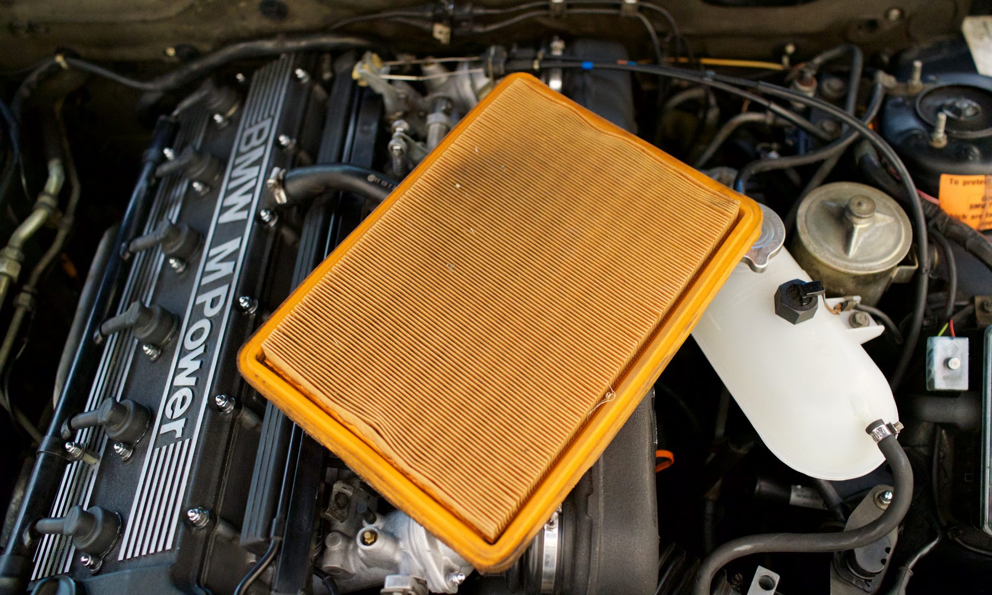
One of the things that always bothered me about my M5 engine bay (as well as other German cars I’ve owned) was that it was covered in cosmoline, which after almost 30 years had become dark yellow and baked to a very hardened finish. I’ve tried various methods of cleaners, steam and elbow grease to remove it from components in situ. I didn’t make nearly as much progress as I would have liked.

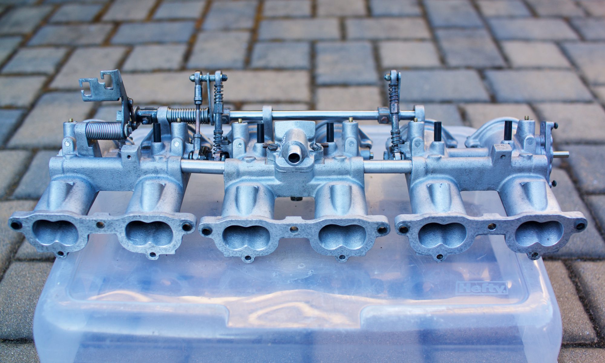
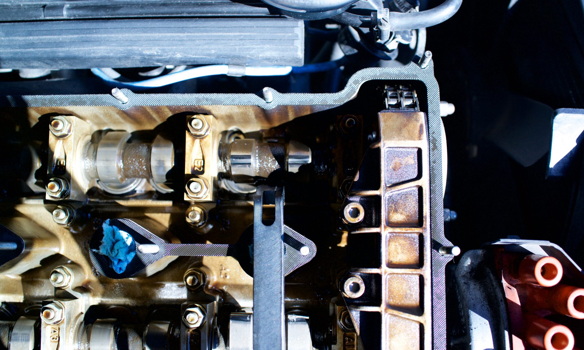
I also thought I had ruined the valve cover when I previously tried to scrub it clean, thinking I had worn through the original paint. When I took the valve cover off for the valve adjustment, my first thought was to get it powder coated professionally. The intake plenum was in similar shape, so I removed that, too, which required me to unbolt the intake runners from the throttle bodies and then remove the boots from the plenum.

I took both pieces to a couple of shops, which described to me all the work required to media blast, thoroughly clean, powder coat and finally bake the two pieces. The quotes are a lot more than I wanted to spend. I then considered a DIY approach and bought some black VHT wrinkle paint and aircraft paint stripper in anticipation of the attempt.

When I removed the intake plenum, I had the aluminum intake runners in hand, which were pretty dirty and oily. I first attempted to soak them in gasoline (premium, of course), which did a remarkably good job of loosening the cosmoline on the exposed portions (most of the part is covered by the flexible boot). However, I felt the gasoline was pretty hazardous with which to work as evidenced by the warping it did to the plastic containers I was using.

I researched some more, and in an interest of using something more green and less hazardous to my health, I came back to Simple Green, which I already had on hand. However, it appears that regular Simple Green isn’t suggested for use with aluminum, as it reacts with the metal and can darken it. I then came across Simple Green Aircraft & Precision Cleaner, which was designed to be safe for aluminum (on aircraft, presumably?). It was worth the premium and I ordered a gallon to start.

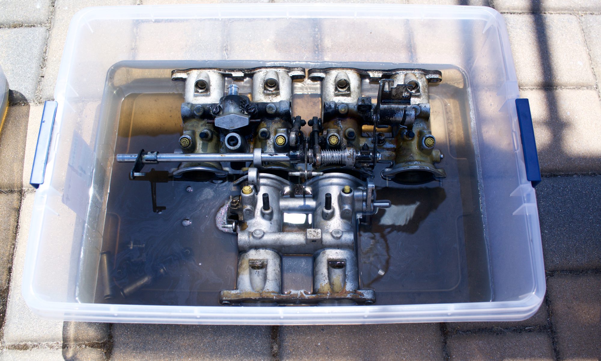
I intended to use it as full strength as recommended, which was a 1:3 dilution with water. Cleaning the valve cover was on the critical path to whatever I was planning to do with it, so I removed the oil breather vent cover from the back side and placed the valve cover, vent cover, and intake runners it in a plastic container with the cleaning solution. I was amazed at how well it removed all the grease and amazingly much of the cosmoline from the paint by just letting it soak with no agitation at all. I was especially pleased to find out that I didn’t actually ruin the valve cover paint, but it was just the baked cosmoline that had become hazy from prior scrubbing. The paint was beautifully pristine under the melting cosmoline.

With this revelation on the wonders of my Simple Green Aircraft cleaner, I decided that the only way to really clean up the throttle bodies was to remove them and soak them in the solution. I anticipated that this would likely be required, so I had already ordered new gaskets and o-rings for the intake runners, balance tubes, bleeder screws, and throttle screw; basically everything required to fully restore the entire intake assembly. I soaked the throttle bodies for days, which melted away 95% of the cosmoline. I used steam, various scrapers and elbow grease to remove the other 95%, which didn’t take long. Finally, I also soaked the intake plenum, which not only had some cosmoline on the exterior, but was covered in oil on the inside.

Once the throttle bodies were removed from the cylinder head, that helped expose all the cosmoline that was baked on there. Not wanting anything to get into the intake valves, I bought some rubber stoppers (size 5), which worked perfectly to keep out liquid and debris during the cleaning process and while the throttle bodies were removed. Sprayed on Simple Green Aircraft and a lot of scrubbing with nylon and brass brushes removed most of the grease and a lot of the cosmoline. I finished the job with a lot of steam and more scrubbing.

I went a little crazy with cleaning all of the little throttle assembly bits, like the brass bypass screws, throttle linkage adjusters and all of the acorn nuts, washers, hex nuts, etc. I ended up buying a heated ultrasonic cleaner, which did a great job cleaning up the fuel injectors. I placed all of the little parts in tea strainer balls, which worked perfectly. I used the Simple Green Aircraft for this, too, and when heated, it worked its cleaning magic even better.

By far, the worst part of this job was removing the old gaskets from the throttle bodies. They were beyond baked on and after 30 years were basically petrified. I read up a lot about the horrors of 3M Roloc discs, bristle discs, scotch bright, aluminum oxide, etc. on aluminum parts and around any open engine. I also read about the dangers of using steel razor blades. So, out of an abundance of caution, I started with CRC Gasket Remover and plastic razor blades. Even with leaving the Gasket Remover to penetrate for hours or even overnight, it did very little to soften the gaskets. Some of the gasket pieces came off in big chunks, leaving mostly the adhesive residue. Other parts seemed impenetrable. I did my best with the plastic blades, which dulled very quickly. In short, I was getting nowhere.

After a day  or so of futility, I decided to throw caution to the wind and ordered 100 steel razor blades. With extreme caution, I honed a technique to remove the gasket little by little. The process was the safest and most effective when the blades were sharp, so I retired them quickly. In the end, I probably ended up using close to 50 blades with repeated application of the gasket remover. This was the most tedious and least gratifying project ever, on any car. I was just happy it was done so I could move forward with the reassembly.

Perform S38 Valve Adjustment

Because the car didn’t come with any records, I had no idea when the valves were last adjusted. As a critical step in baselining the car, I wanted to complete this task and I was now in full DIY mode. Earlier this year, I performed a carbon cleaning on my Audi RS4 and that was the most extensive and invasive engine work I had done to date. That experience, along with a lot of reading, gave me the confidence that this was well within my capabilities.

The first step was to procure the BMW SIR 3012 Tappet Depressor tool. I also purchased a set of angled feeler gauges as well as a new pen-style magnet. The one I had misplaced was the telescoping type, but the non-telescoping one I used turned out to be perfect for the job. I also bought a remote starter switch, which I used to bump the engine to rotate the cams to the proper position before depressing the tappets. Finally, I downloaded an Excel Worksheet, which was super helpful in logging clearances and determining the shims needed.

I basically followed the procedure here, except as noted, I used the remote starter switch across pins 11 and 14 on the diagnostic port instead of turning the engine by hand. With the plug wires removed from the plugs and distributor, there was no risk of the engine starting up. Measuring all of the clearances using the feeler gauges was a little tedious and time consuming, as I often had to check multiple times to ensure I had the proper measurement. I used an ball inflation needle attached to my air compressor. I didn’t heed the warning to remove the excess oil from the cam tray and on the first blast of air on the #6 cylinder, I covered myself in engine oil. Lesson learned!

Once all of the clearances were measured, it turned out that I only had 5 valves out of spec. I let the internet get in my head a little and optimized the intake for 0.30mm and exhaust for 0.33mm. I adjusted the spreadsheet a little to make sure the right shim was acquired. The steps of the feeler gauges, which were primarily marked in inches sometimes made it difficult to zero in on the optimal shim. I didn’t have a set of shims on hand, so I ordered the 5 shims needed. Coincidentally, all were different sizes and none matched another shim that was going to be replaced.

The cam tray remained open (and covered) while I waited for the shims to arrive. I spent that time tackling the cleaning of the valve cover and eventually the entire intake. Once the shims arrived, it was a quick procedure to rotate the engine, depress the tappets, swap out the shims, and confirm the final measurements. It turned out that one of the five shims wasn’t needed as the original shim turned out to be closer to spec than the replacement shim. I felt confident that the valves were now all completely within the optimal clearance.

I’m going to keep the SIR 3012 tool just in case I end up with another S38 or (or S14???) engine in the future.

Retrofit OEM Stereo Head Unit

One of my hobbies in my twenties was car audio. I wasn’t that interested in teeth-rattling bass, but more high-fidelity Natalie Merchant (don’t judge me). For a few of my more recent cars, I would go through the process of collecting somewhat period-correct car audiophile gear from my favorite brand of the time, a/d/s.

The M5 was no exception, but it is the least ideal car to have a nice sound system. The kick panels have no room for decent mid-woofers and I wasn’t going to cut metal. I did the best I could and put in a great-sounding system despite the challenges. There was a big sub on the floor of the backseat, over which the kids had to climb and on which they had to rest their feet. “What is this, Dad???”

Since then, I’ve grappled with modifying the car to make it cooler (e.g., euro bumpers and lights) vs. making it more stock and reversing the mods that were on it. This started with sourcing an OEM exhaust, which wasn’t easy, to replace the loud aftermarket system that came with the car. After that, I decided to embark on getting the whole thing back to stock, thus I ripped out all my hard work on the stereo.

One piece that was hard to track down was a good-condition OEM head unit (a Pioneer KE-81 ZBM-02, if you must know). Like most 30-year-old unicorn parts, I found one on eBay. It came with the code and mostly worked when I hooked it up. I used some DeoxIT to clean up the rheostat and it did wonders to get rid of the static when adjusting the volume. The one problem I had was that I needed to test the cassette, but even I, a self-admitted packrat, had long discarded all of mine.

So, I got back on eBay and purchased the only album that matters. When it arrived and I went to put it in, it just wouldn’t load. Brute force did not seem prudent, so I just left it alone. One morning a couple weeks later, I received an eBay notification (I get many) for a belt kit for this very radio. This serendipity was going to solve all my problems (fingers crossed). It arrived in a hand-written letter envelope shortly thereafter.

I admit that I Googled “car radio repair” a couple times, but I found a web page with some critical information and decided this was a DIY job. I took it apart and sure enough, all of the belts had disintegrated into a gooey tar-like mess. After cleaning up all the parts and putting on the new belts, it was time for the moment of truth…

Overhaul Entire Front Suspension

In continuing my quest to restore the M5 mechanically, I sought to tighten up the front suspension. Rather than diagnose each part, I decided to replace every component. FCP had a kit, but I wanted to upgrade the upper control arm bushings to the Moosehead Engineering spherical bushings, which could be ordered already pressed into Lemforder upper control arms. Thus, I ordered all of the remaining parts of the kit à la carte. I chose Lemforder for every component, except for the steering center link, which was only available from Meyle. The lower control arms are aluminum.

I read up a lot about remove the control arm ball joints and the days of hammering people had gone through to get them to release. I bought a “front-end” tool kit with various pullers and ball joint separators. With the proper tools and my impact wrench, I found it pretty easy to get the key attachment points undone. I removed the entire assembly as a unit from the car and then used the ball joint separator to free the left and right tie rod levers, which were the only parts being reused.

The tie rod levers had some surface rust and would have looked a little out of place connected to all the new shiny parts, so I decided to paint them with POR 15 for aesthetic reasons only. Once they were dry, I was ready to assemble all the components together before installing them on the car. Once I was under the car, I started cleaning adjacent parts and just couldn’t stop. I found it a lot easier to remove the sway bars and some heat shields than try to clean them in place.

When it was all back together, I was very pleased. I had never worked on my suspension before, aside from doing the rear subframe. I immediately took it to our local tire shop for an alignment. Afterwards, the entire front end was so solid and the handling was crisp, as I imagine it was when the car was new. This was one of the biggest and most gratifying jobs I had ever tackled.